This is my first printout using the fused deposition modelling technique. I've made an enclosure for the RaspFPGA board. Preparing CAD files I took the measurements of the second version of the RaspFPGA board but the first version of the RaspFPGA should also fit inside. It has been printed out on the Leapfrog creatr. For the final result look at the pictures below.
wtorek, 25 listopada 2014
piątek, 11 lipca 2014
The second RaspFPGA mezzanine board for Raspberry Pi
This is the second version of the extension card for Raspberry Pi. As the previous one, this circuit connects all GPIO pins of Raspberry Pi to the FPGA chip. I've made a few modifications. Version 2 uses Spartan6 instead of Spartan3, it has 64MB of SDRAM and a small flash memory to store FPPGA configuration. It still leaves all remaining inputs/outputs pins of FPGA for the final user. Now the pin available are less than before because SDRAM occupies many of them. To do not loose this feature one can choose between having SDRAM or having all GPIO available. The choice is done by soldering jumpers in the appropriate places.
The circuit is mechanically and electrically compatible with LCD TFTDisp 4 RaspPAR design published on my blog in March. It contains 25MHz clock source for FPGA, USB to RS232 converter and real time module.
The circuit is mechanically and electrically compatible with LCD TFTDisp 4 RaspPAR design published on my blog in March. It contains 25MHz clock source for FPGA, USB to RS232 converter and real time module.
czwartek, 5 czerwca 2014
4th Scientific Day of the School of Science and Technology
On the 11th of June I will present a poster about optomechanics during poster session in Palazzo Ducale of University of Camerino. The session starts at 10am. Details of the event one can find at 14th Scientific Day Official Poster.
piątek, 21 marca 2014
Lessons of FPGA
La prima lezione
Esercizio 1 in Italian
Slides 1
La seconda lezione
Esercizio 4 in Italian
Esercizio 5 in Italian
Slides 2
La terza lezione
Esercizio 6 in Italian
Esercizio 2 in Italian
Slides 3
Esercizio 1 in Italian
Slides 1
La seconda lezione
Esercizio 4 in Italian
Esercizio 5 in Italian
Slides 2
La terza lezione
Esercizio 6 in Italian
Esercizio 2 in Italian
Slides 3
wtorek, 25 lutego 2014
Brushless DC motor of HDD with Arduino
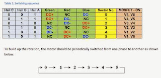
I present a driver for hard drive disk motor based on Arduino and three discreet half H-bridges mounted on proto PCB. Power supply voltage is 12V and current consumption is around 500mA.
Rys. 1 - Theory of driving three phase motor if you use a driver with high-Z output state.
During my first attempt I used L289 chip and I achieved maximal rotary speed around 2900RPM. Using the circuit presented on Rys. 2. I reached the same speed until I was using a simple driving scheme. It means with one phase which breaks the motor. After an upgrade to the scheme from Rys. 1. the rotary speed increased to 7500RPM. Theory, hardware and software are described very well one the website http://elabz.com/.
Rys. 2 - Electric scheme of half H-bridge I used.
Arduino libraries:
BLDC motor Arduino library v0.2
Subskrybuj:
Komentarze (Atom)


